Pobierz prezentację
Pobieranie prezentacji. Proszę czekać

1
Samsung Techwin System kontroli dostępu 2011

2
Spis treści Podstawowe informacje o kontroli dostępu Kontrolery samodzielne (standalone) Centrale Czytniki Akcesoria Kody produktów Konfiguracje systemu Dodatek – dane techniczne
 Centrale Czytniki Akcesoria Kody produktów Konfiguracje systemu Dodatek – dane techniczne")
3
Wprowadzenie Kontrola dostępu (ang. Access Control) jest systemem, który pozwala na autoryzację dostępu do wyznaczonych obszarów i zasobów w określonej lokalizacji (np. budynek) Warunki przyznania dostępu KOMU GDZIE JAK KIEDY Kontrolowane punkty dostępu Autoryzowani użytkownicy Określone ramy czasowe Indywidualne definicje dostępu
 jest systemem, który pozwala na autoryzację dostępu do wyznaczonych obszarów i zasobów w określonej lokalizacji (np. budynek) Warunki przyznania dostępu KOMU GDZIE JAK KIEDY Kontrolowane punkty dostępu Autoryzowani użytkownicy Określone ramy czasowe Indywidualne definicje dostępu.")
4
Wprowadzenie (c.d.) Zamki i klucze Zabezpieczają drzwi Klucz zawsze otworzy zamek, niezależnie od czasu Zgubione klucze = wymiana zamka (ryzyko włamania) Brak rejestracji wejść Dużo różnych zamków = ciężki pęk kluczy Utrata wszystkich kluczy = wymiana wszystkich zamków Elektroniczna kontrola dostępu Zabezpiecza drzwi Różne przedziały czasy i poziomy dostępu Zgubioną kartę można deaktywować Dowolna karta może otwierać wszystkie lub wybrane drzwi Pełna historia (zapis) użycia kart Nie trzeba wymieniać dobrych zamków Monitorowanie stanu drzwi (otwarcie siłowe lub przytrzymanie drzwi) Definicje dostępu mogą być dowolną kombinacją kart, kodów PIN i danych biometrycznych użytkowników
 Zamki i klucze Zabezpieczają drzwi Klucz zawsze otworzy zamek, niezależnie od czasu Zgubione klucze = wymiana zamka (ryzyko włamania) Brak rejestracji wejść Dużo różnych zamków = ciężki pęk kluczy Utrata wszystkich kluczy = wymiana wszystkich zamków Elektroniczna kontrola dostępu Zabezpiecza drzwi Różne przedziały czasy i poziomy dostępu Zgubioną kartę można deaktywować Dowolna karta może otwierać wszystkie lub wybrane drzwi Pełna historia (zapis) użycia kart Nie trzeba wymieniać dobrych zamków Monitorowanie stanu drzwi (otwarcie siłowe lub przytrzymanie drzwi) Definicje dostępu mogą być dowolną kombinacją kart, kodów PIN i danych biometrycznych użytkowników")
5
Kontrola dostępu Samsung Techwin – definicje dostępu Niski Fizyczna / Klucz elektroniczny Przykład – karta dostępu Średni Dane znane tylko użytkownikowi Przykład – kod PIN Wysoki Unikalna cecha każdego użytkownika Przykład – odcisk palca

6
Kontrola dostępu Samsung Techwin – Zakres dostępnych rozwiązań CZYTNIKI SAMODZIELNE (STANDALONE) Podstawowy poziom kontroli, jeden sposób weryfikacji Zabezpieczenie średniego poziomu, wymagane 2 sposoby weryfikacji Wysokie bezpieczeństwo, wymagane 3 sposoby weryfikacji Możliwość współpracy z PC dla czytników kontroli czasu pracy OPROGRAMOWANIE, INTELIGENTNE KONTROLERY I CZYTNIKI Skalowalne oprogramowanie, bazujące na MS SQL Server 2008 Przetwarzanie rozproszone Kontrolery dla 1,2,3 i 4 drzwi Czytniki zbliżeniowe / Smart, z klawiaturą dla PIN oraz biometryczne Praca w sieci TCP/IP Integracja z systemami CCTV Pełne zarządzanie i kontrola całego systemu
 Podstawowy poziom kontroli, jeden sposób weryfikacji Zabezpieczenie średniego poziomu, wymagane 2 sposoby weryfikacji Wysokie bezpieczeństwo, wymagane 3 sposoby weryfikacji Możliwość współpracy z PC dla czytników kontroli czasu pracy OPROGRAMOWANIE, INTELIGENTNE KONTROLERY I CZYTNIKI Skalowalne oprogramowanie, bazujące na MS SQL Server 2008 Przetwarzanie rozproszone Kontrolery dla 1,2,3 i 4 drzwi Czytniki zbliżeniowe / Smart, z klawiaturą dla PIN oraz biometryczne Praca w sieci TCP/IP Integracja z systemami CCTV Pełne zarządzanie i kontrola całego systemu")
7
Kontrola dostępu Samsung Techwin System kontroli dostępu Samsung Techwin oferuje nowocześnie i estetycznie zaprojektowane produkty, pozwalające na realizację efektywnych kosztowo rozwiązań, dostosowanych do indywidualnych potrzeb i możliwości finansowych klienta. Linia czytników samodzielnych (standalone) oferuje najwyższą efektywność kosztową dla małych systemów, przy zachowaniu wysokiego bezpieczeństwa systemu. Połączenie czytników biometrycznych (odcisk palca), klawiatury dla wprowadzania kodu PIN oraz technologii zbliżeniowej gwarantuje najwyższy poziom bezpieczeństwa w każdych warunkach. Wyższą klasę bezpieczeństwa zapewnia system kontroli dostępu SAMS (ang. Samsung Access Management System). Bazując na wysoce stabilnej i sprawdzonej technologii baz danych MS SQL Server 2008 i wspierając rozmaite protokoły komunikacyjne, integrację z systemami CCTV oraz pełne zarządzanie i kontrolę całego systemu SAMS stanowi doskonałe rozwiązanie dla dużych instalacji.
 oferuje najwyższą efektywność kosztową dla małych systemów, przy zachowaniu wysokiego bezpieczeństwa systemu. Połączenie czytników biometrycznych (odcisk palca), klawiatury dla wprowadzania kodu PIN oraz technologii zbliżeniowej gwarantuje najwyższy poziom bezpieczeństwa w każdych warunkach. Wyższą klasę bezpieczeństwa zapewnia system kontroli dostępu SAMS (ang. Samsung Access Management System). Bazując na wysoce stabilnej i sprawdzonej technologii baz danych MS SQL Server 2008 i wspierając rozmaite protokoły komunikacyjne, integrację z systemami CCTV oraz pełne zarządzanie i kontrolę całego systemu SAMS stanowi doskonałe rozwiązanie dla dużych instalacji..")
8
Co to są czytniki samodzielne ? Czytniki samodzielne (ang. standalone): nie wymagają podłączenia z komputerem dla swojego działania mogą być zaprogramowanie lokalnie, natychniast po podłączeniu zasilania administracja poziomami i sposobami dostępu, kartami, itp. może być dokonywana lokalnie, bezpośrednio z poziomu urządzenia
: nie wymagają podłączenia z komputerem dla swojego działania mogą być zaprogramowanie lokalnie, natychniast po podłączeniu zasilania administracja poziomami i sposobami dostępu, kartami, itp. może być dokonywana lokalnie, bezpośrednio z poziomu urządzenia.")
9
Cechy czytników samodzielnych Efektywna kosztowo kontrola drzwi Opcje dostępu zbliżeniowego, kart dostępu, kodu PIN oraz odcisków palców Kontrola blokady drzwi – Blokada przy zasilaniu / Blokada przy braku zasilania Produkty zapewniające zwiększone bezpieczeństwo dzięki różnorodnym sposobom weryfikacji użytkownika oraz wandaloodpornym obudowom

10
Czytniki samodzielne (standalone) SSA-S1000 SSA-S1000V SSA-S2000 SSA-S2000V SSA- S3010/3020/3040 SSA- S3011/3021/3041 SSA- S3010/3020/3040 SSA- S3011/3021/3041 SSA-S2100 SSA-S2101 SSA-S2100 SSA-S2101
 SSA-S1000 SSA-S1000V SSA-S2000 SSA-S2000V SSA- S3010/3020/3040 SSA- S3011/3021/3041 SSA- S3010/3020/3040 SSA- S3011/3021/3041 SSA-S2100 SSA-S2101 SSA-S2100 SSA-S2101")
11
Czytnik samodzielny – SSA-S1000 / S1000V Zbliżeniowy czytnik & kontroler Efektywna kosztowo kontrola pojedynczych drzwi Estetyczny i nowoczesny design Idealny do niewielkich i prostych instalacji Opcja obudowy wandaloodpornej Funkcjonalność – Podstawowa kontrola dostępu – Samodzielność działania (nie wymagany PC ani oprogr.) – Obsługa do 512 użytkowników – Zamki typu Power Fail Safe lub Fail Secure (blokada drzwi przy zasilaniu / Blokada przy braku zasilania) – Shadow Cards Model wandaloodporny (V) – Obudowa wodo i pyłoodporna (IP68) Dane techniczneDane techniczne Układ połączeń KonfiguracjeUkład połączeńKonfiguracje
 – Obsługa do 512 użytkowników – Zamki typu Power Fail Safe lub Fail Secure (blokada drzwi przy zasilaniu / Blokada przy braku zasilania) – Shadow Cards Model wandaloodporny (V) – Obudowa wodo i pyłoodporna (IP68) Dane techniczneDane techniczne Układ połączeń KonfiguracjeUkład połączeńKonfiguracje")
12
Czytnik samodzielny – SSA-S2000 / S2000V Czytnik / kontroler zbliżeniowy + kod PIN Efektywny kosztowo, dwufunkcyjny kontroler dla pojedynczych drzwi Idealny dla niewielkich instalacji Opcja obudowy wandaloodpornej Opcja współpracy z drugim czytnikiem (czytnnik wyjścia) Funkcjonalność – Technologia zbliżeniowa + kod PIN (opcje tylko zbliżeniowy lub tylko PIN) – Samodzielność działania (nie wymagany PC ani oprogr.) – Obsługa do 512 użytkowników – 5 wejść, 4 wyjścia – programowalne – Obsługa przymusu – Zamki typu Power Fail Safe lub Fail Secure (blokada drzwi przy zasilaniu / Blokada przy braku zasilania) Model wandaloodporny (V) – Obudowa wodoodporna (IP66) Dane techniczneUkład połączeńDane techniczneUkład połączeń KonfiguracjeKonfiguracje
 Funkcjonalność – Technologia zbliżeniowa + kod PIN (opcje tylko zbliżeniowy lub tylko PIN) – Samodzielność działania (nie wymagany PC ani oprogr.) – Obsługa do 512 użytkowników – 5 wejść, 4 wyjścia – programowalne – Obsługa przymusu – Zamki typu Power Fail Safe lub Fail Secure (blokada drzwi przy zasilaniu / Blokada przy braku zasilania) Model wandaloodporny (V) – Obudowa wodoodporna (IP66) Dane techniczneUkład połączeńDane techniczneUkład połączeń KonfiguracjeKonfiguracje")
13
Czytnik samodzielny – SSA-S2100 / S2101 Kontroler / czytnik zbliżeniowy, kart Smart, kodu PIN, kontroli czasu pracy Doskonały dla aplikacji o wysokich wymaganiach Kontrola czasu pracy Praca samodzielna lub sieciowe raportowanie i administrowanie za pomocą aplikacji dla systemu Microsoft Windows Możliwość podłączenia drugiego czytnika Funkcjonalność – Do 20 000 użytkowników i 20 000 zdarzeń – Kombinacje karty zbliżeniowej i kodu PIN – 4 wejścia i 4 wyjścia – programowalne + harmonogram – Funkcja uzbrojenia / rozbrojenia (interfejs do systemu alarmowego) – Harmonogramy – Tryb podwójnej autoryzacji (dwie osoby) – Obsługa przymusu – Zamki typu Power Fail Safe lub Fail Secure (blokada drzwi przy zasilaniu / Blokada przy braku zasilania) – Zarządzanie bezpośrednio z czytnika lub za pomocą oprogramowania sieciowego Dane techniczneUkład połączeń
 – Harmonogramy – Tryb podwójnej autoryzacji (dwie osoby) – Obsługa przymusu – Zamki typu Power Fail Safe lub Fail Secure (blokada drzwi przy zasilaniu / Blokada przy braku zasilania) – Zarządzanie bezpośrednio z czytnika lub za pomocą oprogramowania sieciowego Dane techniczneUkład połączeń")
14
Czytnik samodzielny – SSA-S3010 / S3011 Series Rozpoznawanie odcisków palców, karty zbliżeniowe i Smart, kod PIN, kontrola czasu pracy Potrójna autoryzacja, w tym biometryczna Doskonały do aplikacji o wysokich wymaganiach bezpieczeństwa Kontrola czasu pracy Praca samodzielna lub sieciowe raportowanie i administrowanie za pomocą aplikacji dla systemu Microsoft Windows Możliwość podłączenia drugiego czytnika Funkcjonalność – Do 4000 użytkowników weryfikowanych odciskiem palca – Wszystkie kombinacje odcisku palca, karty zbliżeniowej oraz kodu PIN – 4 wejścia i 4 wyjścia – programowalne + harmonogram – Funkcja uzbrojenia / rozbrojenia (interfejs do systemu alarmowego) – Harmonogramy – Tryb podwójnej autoryzacji (dwie osoby) – Obsługa przymusu – Zamki typu Power Fail Safe lub Fail Secure (blokada drzwi przy zasilaniu / Blokada przy braku zasilania) – Zarządzanie bezpośrednio z czytnika lub za pomocą oprogramowania sieciowego Technical Data LinkConnection Diagram Link
 – Harmonogramy – Tryb podwójnej autoryzacji (dwie osoby) – Obsługa przymusu – Zamki typu Power Fail Safe lub Fail Secure (blokada drzwi przy zasilaniu / Blokada przy braku zasilania) – Zarządzanie bezpośrednio z czytnika lub za pomocą oprogramowania sieciowego Technical Data LinkConnection Diagram Link")
15
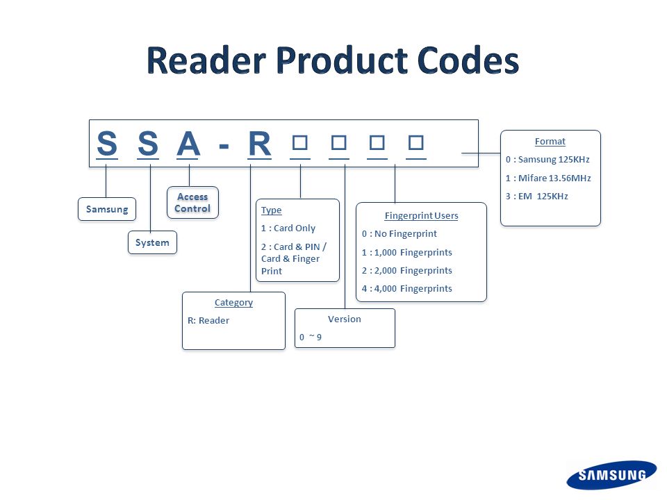
Oznaczenia produktów – czytniki samodzielne

16
Czytniki samodzielne - podsumowanie ModelGłówne funkcjeAplikacja SSA-S1000Samsung 125KHz Proximity / 512 użytkowników. Efektywny kosztowo, samodzielny kontroler o podstawowej funkcjonalności SSA-S1000V Samsung 125KHz Proximity / 512 użytkowników, obudowa wandaloodporna. Efektywny kosztowo, samodzielny kontroler o podstawowej funkcjonalności dla aplikacji o zwiększonym ryzyku wandalizmu SSA-S2000 Hybrydowy (dualny) kontroler – karta zbliżeniowa + PIN, 512 użytkowników Dla instalacji o podwyższonych wymogach bezpieczeństwa i podwójnej autoryzacji SSA-S2000V Hybrydowy (dualny) kontroler – karta zbliżeniowa + PIN, 512 użytkowników, obudowa wandaloodporna Dla instalacji o podwyższonych wymogach bezpieczeństwa i podwójnej autoryzacji, w instalacjach o zwiększonym ryzyku wandalizmu SSA-S2100 Series Karta zbliżeniowa / Smart + PIN, kontrola czasu pracy. 20 000 użytkowników. Opcjonalne sieciowe oprogramowanie administracyjne. Dla instalacji o wysokich wymaganiach bezpieczeństwa oraz z wymogami kontroli czasu pracy, funkcji antypasback oraz uzbrajania i rozbrajania systemu. SSA-S3010 Series Czytnik biometryczny (odcisk palca) + karta zbliżeniowa / Smart + PIN, kontrola czasu pracy. 20 000 użytkowników. Opcjonalne sieciowe oprogramowanie administracyjne. Aplikacje o najwyższym poziomie zabezpieczeń, wymagające kontroli biometrycznej, kontroli czasu pracy, funkcji antypasback oraz uzbrajania / rozbrajania systemu. Wszystkie modele Kontrola dostępu Kontrola zamka Samodzielne działanie, do pracy nie jest wymagany żaden komputer ani oprogramowanie Efektywne kosztowo instalacje samodzielnych czytników z kontrolą zamków.
 kontroler – karta zbliżeniowa + PIN, 512 użytkowników Dla instalacji o podwyższonych wymogach bezpieczeństwa i podwójnej autoryzacji SSA-S2000V Hybrydowy (dualny) kontroler – karta zbliżeniowa + PIN, 512 użytkowników, obudowa wandaloodporna Dla instalacji o podwyższonych wymogach bezpieczeństwa i podwójnej autoryzacji, w instalacjach o zwiększonym ryzyku wandalizmu SSA-S2100 Series Karta zbliżeniowa / Smart + PIN, kontrola czasu pracy użytkowników. Opcjonalne sieciowe oprogramowanie administracyjne. Dla instalacji o wysokich wymaganiach bezpieczeństwa oraz z wymogami kontroli czasu pracy, funkcji antypasback oraz uzbrajania i rozbrajania systemu. SSA-S3010 Series Czytnik biometryczny (odcisk palca) + karta zbliżeniowa / Smart + PIN, kontrola czasu pracy użytkowników. Opcjonalne sieciowe oprogramowanie administracyjne. Aplikacje o najwyższym poziomie zabezpieczeń, wymagające kontroli biometrycznej, kontroli czasu pracy, funkcji antypasback oraz uzbrajania / rozbrajania systemu. Wszystkie modele Kontrola dostępu Kontrola zamka Samodzielne działanie, do pracy nie jest wymagany żaden komputer ani oprogramowanie Efektywne kosztowo instalacje samodzielnych czytników z kontrolą zamków..")
17
Czytniki samodzielne – podsumowanie

18
Kontrolery (panele) inteligentne Kontrolery (panele) zapewniają dystrybucję sygnałów i obsługę interfejsów kontroli dostępu: czytniki, klawiatury, wejścia i wyjścia oraz administrację systemu z poziomu komputera / oprogramowania.
 inteligentne Kontrolery (panele) zapewniają dystrybucję sygnałów i obsługę interfejsów kontroli dostępu: czytniki, klawiatury, wejścia i wyjścia oraz administrację systemu z poziomu komputera / oprogramowania.")
19
Kontrolery (panele) inteligentne – dystrybucja sygnałów Dystrybucja sygnałów pozwala każdemu kontrolerowi działać całkowicie niezależnie od komputera nadzorującego. Znaczna większość procesów odbywa się w samym kontrolerze. Kontroler przejmuje zadania nadzoru drzwi, alarmów, zdarzeń sprzętowych, wejść / wyjść, etc. Jednocześnie umożliwia to odciążenie komputera nadzorującego i przeznaczenie jego zasobów na obsługę reakcji alarmowych, współpracę z bazą danych, itp.

20
Kontrolery inteligentne Zaawansowana technologia za przystępną cenę Intelligent control of 1,2,3 or 4 Doors Communication: TCP/IP, RS232, RS485 / RS422 Data Continuity after power failure Programmable Inputs / Outputs Up to 50,000 users Up to 50,000 event buffer Wiegand compatible readers

21
Intelligent Controllers State-of-the-art Controllers at affordable prices Single Door Controller Small to Medium Business Safe non-volatile Flash Data Memory - for business continuity Duress Mode Function Site Arm / Disarm Function Single door controller Up to 50,000 users / 50,000 event buffer Versatile 5 input / 4 output Select TCP/IP, RS232, RS285 or RS422 communication Four Door Controller Medium to Large Business Safe non-volatile Flash Data Memory - for business continuity Duress Mode Function Site Arm / Disarm Function Up to four doors controlled Up to 50,000 users / 29,500 event buffer Versatile 15 input / 15 output Select TCP/IP, RS232, RS285 or RS422 communication Link to : Installation Network Configuration Serial CommunicationInstallationNetwork ConfigurationSerial Communication Four Door: Reader Connection Lock ConnectionReader ConnectionLock Connection Single Door: Reader Connection Input Connection Lock ConnectionReader ConnectionInput ConnectionLock Connection

22
Intelligent Controller – Questions? Link to : Installation Network Configuration Serial CommunicationInstallationNetwork ConfigurationSerial Communication Four Door: Reader Connection Lock ConnectionReader ConnectionLock Connection Single Door: Reader Connection Input Connection Lock ConnectionReader ConnectionInput ConnectionLock Connection

23
Readers Comprehensive range of readers to satisfy challenging security environments

24
Samsung have developed a range of highly aesthetic readers, which transmit user credentials to the Intelligent Controllers. Reader variations include Slim Line, Vandal Resistant, PIN Number and Biometric Fingerprint with a range of card technologies.

25
Readers – R1000 / R1100 Comprehensive range of readers to satisfy challenging security environments Elegant looking proximity / smart card / EM reader Read Range of 10cm Both units use the same weatherproof (IP66)epoxy moulding, so are interchangeable depending on the wall condition or aesthetic preference Can be installed on metal door frame or on a wall Wiegand output Link to Technical Specification Link to Wiring DiagramLink to Technical Specification Link to Wiring Diagram
epoxy moulding, so are interchangeable depending on the wall condition or aesthetic preference Can be installed on metal door frame or on a wall Wiegand output Link to Technical Specification Link to Wiring DiagramLink to Technical Specification Link to Wiring Diagram")
26
Readers – R1000V / R1100V Comprehensive range of readers to satisfy challenging security environments Elegant looking proximity / smart card / EM reader which can be mounted on a metal door frame or on a wall. Vandal resistant with a high level of weatherproofing (IP68) for challenging environmental conditions Wiegand output Link to Technical Specification Link to Technical Specification Link to Wiring DiagramLink to Wiring Diagram
 for challenging environmental conditions Wiegand output Link to Technical Specification Link to Technical Specification Link to Wiring DiagramLink to Wiring Diagram.")
27
Readers – R2000 / R2000V Comprehensive range of readers to satisfy challenging security environments Elegant looking proximity / smart card / EM reader with back-lit keypad for PIN entry in dark conditions. Can be mounted on metal door frame or wall. Vandal option is IP68 and features the capacitive touch sensitive keypad Link to Technical Specification 2000Link to Technical Specification 2000 Link to Wiring Diagram 2000Link to Wiring Diagram 2000 Link to Technical Specification 2000VLink to Technical Specification 2000V Link to Wiring Diagram 2000VLink to Wiring Diagram 2000V

28
Readers – R2010 / R2011 Comprehensive range of readers to satisfy challenging security environments Fingerprint recognition and proximity / smart card reader for high security applications Auto touch sensor for fingerprint only recognition. Operating mode selectable by individual ID (RF Only, fingerprint only, RF + fingerprint) Link to Technical Specification Link to Technical Specification Link to Wiring DiagramLink to Wiring Diagram
 Link to Technical Specification Link to Technical Specification Link to Wiring DiagramLink to Wiring Diagram.")
30
Reader – Questions? Comprehensive range of readers to satisfy challenging security environments

31
Software Samsung Access Management Software SAMS Basic and SAMS Pro (Video Integration) have a free licence which has full functionality and includes the database engine (SQL Server 2005 Express) up to the level of 20 doors OR 100 users.
 have a free licence which has full functionality and includes the database engine (SQL Server 2005 Express) up to the level of 20 doors OR 100 users.")
32
Software Samsung Access Management Software SAMS is a programmable, integrated, computer based security system software package that provides access control, alarm point monitoring, access control administration and monitoring to the rest of the hardware system. Windows based Server and Client, SAMS is menu driven and easy to use.

33
Software – SAMS Basic and Basic Lite Samsung Access Management Software Scalable access management software built on an SQL Server 2005. Dual Monitor support Integrated Monitoring with site map Easy In/Output control and monitoring with Door, Sensor, Alarm Icon on the site map Server (SAMS Basic)/ Client (Basic Lite) network configuration Software Architecture System Configuration 1 System Configuration 2
/ Client (Basic Lite) network configuration Software Architecture System Configuration 1 System Configuration 2.")
34
Software – SAMS Pro and Pro Lite Samsung Access Management Software Video Integration, Command and Control maps. Scalable access management software built on an SQL Server 2005. Dual Monitor support Integrated Monitoring with site map Easy In/Output control and monitoring with Door, Sensor, Alarm Icon on the site map Server (SAMS Pro)/ Client (Pro Lite) network configuration Software Architecture System Configuration 1 System Configuration 2
/ Client (Pro Lite) network configuration Software Architecture System Configuration 1 System Configuration 2.")
35
Software – Questions? Samsung Access Management Software Basic / Basic Lite Pro / Pro Lite Software Architecture System Configuration 1 System Configuration 2 Software Architecture System Configuration 1 System Configuration 2

36
Appendix / Technical Data SSA-S1000(V) - Connection Data / Setup Data / Technical Data SSA-S2000(V) – Connection Data / Panel Description / Card Registration / Setup / Technical Data SSA-S21XX / S30XX – Panel Description / Basic Installation / Network Diagram / Connection Data / Technical Data SSA-P4XX / P1XX – Intelligent Controller / Installation / Network Configuration / Serial Communications / SSA-P4XX Reader + RTE Connection / SSA-P4XX Lock Connection / SSA-P1XX Reader Connection / SSA-P1XX Input Connection / SSA-P1XX Lock Connection 1 Door Reader SSA-R1000 + R1100 / Connection Data / Technical Data Reader SSA-R1000V + R1100V / Connection Data / Technical Data Reader SSA-R2000 / Connection Data / Technical Data Reader SSA-R2000V / Connection Data / Technical Data Reader SSA-R2010 / 3010 Series / Connection Data / Technical Data Software – Basic / Architecture / System Configuration Software – Pro / Architecture / System Configuration
 - Connection Data / Setup Data / Technical Data SSA-S2000(V) – Connection Data / Panel Description / Card Registration / Setup / Technical Data SSA-S21XX / S30XX – Panel Description / Basic Installation / Network Diagram / Connection Data / Technical Data SSA-P4XX / P1XX – Intelligent Controller / Installation / Network Configuration / Serial Communications / SSA-P4XX Reader + RTE Connection / SSA-P4XX Lock Connection / SSA-P1XX Reader Connection / SSA-P1XX Input Connection / SSA-P1XX Lock Connection 1 Door Reader SSA-R R1100 / Connection Data / Technical Data Reader SSA-R1000V + R1100V / Connection Data / Technical Data Reader SSA-R2000 / Connection Data / Technical Data Reader SSA-R2000V / Connection Data / Technical Data Reader SSA-R2010 / 3010 Series / Connection Data / Technical Data Software – Basic / Architecture / System Configuration Software – Pro / Architecture / System Configuration")
37
Exit Button DC 12V(+) Power Door Contact DeviceWiring Power Connect +12V of power supply to Red wire. Connect GND of power supply to Black wire. Door Sensor Connect COM terminal of door sensor to Blue wire of door sensor input. Connect NO terminal of door sensor to GND of power supply. Exit Button Connect Green wire of exit button input to one wire between wires of exit button. Connect GND wire of power supply to the other wire. Standalone Controller – SSA-S1000 / S1000V – Connection Data Proximity Access Controller BACK

38
Standalone Controller – SSA-S1000 / S1000V – Connection Data Proximity Access Controller Door Lock Alarm Device DC 12V(+) Power DeviceWiring Power Connect +12V of power supply to Red wire. Connect GND of power supply to Black wire. Door Lock Connect (+) wire of door lock to +12V wire of power supply. Connect (-) wire of door lock to white wire of reader module. Alarm Connect (+) wire of Alarm to +12V wire of power supply. Connect (-) wire of Alarm to purple wire of reader module. Lock Type Select In a power fail safe, connect GND wire of power supply to Yell ow wire of door lock type input. In a power fail secure, put a floating state on Yellow wire of d oor lock type input. BACK
 wire of door lock to +12V wire of power supply. Connect (-) wire of door lock to white wire of reader module. Alarm Connect (+) wire of Alarm to +12V wire of power supply. Connect (-) wire of Alarm to purple wire of reader module. Lock Type Select In a power fail safe, connect GND wire of power supply to Yell ow wire of door lock type input. In a power fail secure, put a floating state on Yellow wire of d oor lock type input. BACK.")
39
Step 1 1) Turn the power off 2) Short White & Green & Yellow wire Step 2 1) Turn the power on 2) All red led will be turned on and off twice with buzzer 3) Turn the power off Step 3 1) Disconnect White & Green & Yellow wire 2) Turn power ON 3) Present the card that you wish to use as master card 4) Master card has been registered SSA-S1000 / S1000V Standalone Controller Standalone Controller – SSA-S1000 / S1000V – Setup Data Proximity Access Controller BACK
 Turn the power off 2) Short White & Green & Yellow wire Step 2 1) Turn the power on 2) All red led will be turned on and off twice with buzzer 3) Turn the power off Step 3 1) Disconnect White & Green & Yellow wire 2) Turn power ON 3) Present the card that you wish to use as master card 4) Master card has been registered SSA-S1000 / S1000V Standalone Controller Standalone Controller – SSA-S1000 / S1000V – Setup Data Proximity Access Controller BACK")
40
Standalone Controller – SSA-S1000 / S1000V – Technical Data Proximity Access Controller BACK

41
DC +12V(Red) GND (Black ) Power Exit Button Yellow with Red stripe Door Contact Connection Green COM NC NO COM NO GND (Black ) PIR Sensor IN#1(Orange) IN#2(Green with White stripe) IN#3(Brown) GND(Black ) PIR Sensor Auxiliary Input #1~#3 SSA-S2000 / S2000V Standalone Controller Standalone Controller – SSA-S2000 / S2000V – Connection Data Proximity and PIN Access Controller BACK
 GND (Black ) Power Exit Button Yellow with Red stripe Door Contact Connection Green COM NC NO COM NO GND (Black ) PIR Sensor IN#1(Orange) IN#2(Green with White stripe) IN#3(Brown) GND(Black ) PIR Sensor Auxiliary Input #1~#3 SSA-S2000 / S2000V Standalone Controller Standalone Controller – SSA-S2000 / S2000V – Connection Data Proximity and PIN Access Controller BACK")
42
NO(Blue with White stripe) NC(White with Red stripe) NO (Purple) NC(Purple with White stripe) COM (White) X Alarm - + Alarm Connection Door Lock GND (Black ) DC+12V(Red ) DC+12V Power - + POWER FAIL SAFE POWER FAIL SECURE DC+12V(Red ) GND (Black ) Exit Reader GND (Black ) DC+12V(Red ) DATA0(Pink ) DATA1(Cyan ) DATA0(Pink ) * Connection of POWER FAIL SAFE: Door Lock * Connection of POWER FAIL SECURE: Door Lock COM(Gray with Red stripe) DATA1(Cyan ) SSA-S2000 / S2000V Standalone Controller Standalone Controller – SSA-S2000 / S2000V – Connection Data Proximity and PIN Access Controller BACK
 NC(White with Red stripe) NO (Purple) NC(Purple with White stripe) COM (White) X Alarm - + Alarm Connection Door Lock GND (Black ) DC+12V(Red ) DC+12V Power - + POWER FAIL SAFE POWER FAIL SECURE DC+12V(Red ) GND (Black ) Exit Reader GND (Black ) DC+12V(Red ) DATA0(Pink ) DATA1(Cyan ) DATA0(Pink ) * Connection of POWER FAIL SAFE: Door Lock * Connection of POWER FAIL SECURE: Door Lock COM(Gray with Red stripe) DATA1(Cyan ) SSA-S2000 / S2000V Standalone Controller Standalone Controller – SSA-S2000 / S2000V – Connection Data Proximity and PIN Access Controller BACK")
43
When the Main Unit operates in Selection Mode, LED is flashing. When a registered Card (or PIN) is read or exit button is pressed, LED will be on for 3 seconds along with the "do-mi-sol-do" melody, and Lock will be opened. When an unregistered Card (or PIN) is read, LED will be on for 2 seconds along with the "sol-do-sol-do" melody. When the Main Unit operates in normal mode LED is flashing every second. Keypad LED Indicator SSA-S2000 / S2000V Standalone Controller Standalone Controller – SSA-S2000 / S2000V – Front Panel Description Proximity and PIN Access Controller BACK
 is read or exit button is pressed, LED will be on for 3 seconds along with the do-mi-sol-do melody, and Lock will be opened. When an unregistered Card (or PIN) is read, LED will be on for 2 seconds along with the sol-do-sol-do melody. When the Main Unit operates in normal mode LED is flashing every second. Keypad LED Indicator SSA-S2000 / S2000V Standalone Controller Standalone Controller – SSA-S2000 / S2000V – Front Panel Description Proximity and PIN Access Controller BACK.")
44
Step 1 1)Turn the power off 2)Short Green & Orange with white stripe wires 3)Turn the power on 4)3 color LED blinking with beep sound indicates the success of initialization. Step 2 1)Disconnect Orange & Orange with white stripe wires 2)3 color LED keep blinking (Initial Mode) Step 3 1) Select the Operation Mode - Card Only (0,1,ENT) - Card + PIN (0,2,ENT) - PIN Only (0,3,ENT) - Card / PIN Combination (0,5,ENT) 2) Present the card that you wish to use as master card 3) Register Users or Present Master card again to exit registration Mode Master Card User Access Cards or PINs SSA-S2000 / S2000V Standalone Controller Standalone Controller – SSA-S2000 / S2000V – Master Card Registration Proximity and PIN Access Controller BACK
Disconnect Orange & Orange with white stripe wires 2)3 color LED keep blinking (Initial Mode) Step 3 1) Select the Operation Mode - Card Only (0,1,ENT) - Card + PIN (0,2,ENT) - PIN Only (0,3,ENT) - Card / PIN Combination (0,5,ENT) 2) Present the card that you wish to use as master card 3) Register Users or Present Master card again to exit registration Mode Master Card User Access Cards or PINs SSA-S2000 / S2000V Standalone Controller Standalone Controller – SSA-S2000 / S2000V – Master Card Registration Proximity and PIN Access Controller BACK.")
45
Initial Setup is required upon the first time the unit is powered-up in order to operate the unit properly. 1) Registration of RF Cards for RF CARD ONLY MODE 2) Registration of RF Cards with PINs for RF CARD + PIN MODE 3) Registration of PIN ONLY MODE 4) Registration of RF/PIN Combination MODE 1) Registration of RF Cards for RF CARD ONLY MODE2) Registration of RF Cards with PINs for RF CARD + PIN MODE (1) Apply 12VDC to the unit. All 3 LEDs will be flashing along with a powered-up melody (do mi sol me do..do mi sol do~). (2) Press 0,1,ENT from the keypad. (RF CARD ONLY MODE ) (3) Present RF Cards as follow to register Master Card and User Access Cards. (1) Apply 12VDC to the unit. All 3 LEDs will be flashing along with a powered-up melody (do mi sol me do..do mi sol do~). (2) Press 0,2,ENT from the keypad. (RF CARD + PIN MODE ) (3) Present RF Cards as follow to register Master Card and User Access Cards + 4~6 digit Personal Identification Number (PIN) for each User Access Card. (4) The first card read becomes the Master Card and the following RF Cards are registered as User Access Cards. Once all User Access Cards have been registered, present the Master Card again to complete the registration. (Please keep the Master Card in a secure location for future changes.) (5) Now, the Main Unit is entered into the normal operation mode with factory defaulted settings. (4) The first card read becomes the Master Card and the following RF Cards + PINs are registered as User Access Cards with assigned PINs. Once all User Access Cards and PINs have been registered, present the Master Card again to complete the registration. (Please keep the Master Card in a secure location for future changes.) (5) Now, the Main Unit is entered into the normal operation mode with factory defaulted settings. Master CardUser Access CardsMaster Card again to end task Master Card User Access Cards + PINs Master Card again to end task SSA-S2000 / S2000V Standalone Controller Standalone Controller – SSA-S2000 / S2000V – Initial Setup Proximity and PIN Access Controller BACK
 Registration of RF Cards for RF CARD ONLY MODE 2) Registration of RF Cards with PINs for RF CARD + PIN MODE 3) Registration of PIN ONLY MODE 4) Registration of RF/PIN Combination MODE 1) Registration of RF Cards for RF CARD ONLY MODE2) Registration of RF Cards with PINs for RF CARD + PIN MODE (1) Apply 12VDC to the unit. All 3 LEDs will be flashing along with a powered-up melody (do mi sol me do..do mi sol do~). (2) Press 0,1,ENT from the keypad. (RF CARD ONLY MODE ) (3) Present RF Cards as follow to register Master Card and User Access Cards. (1) Apply 12VDC to the unit. All 3 LEDs will be flashing along with a powered-up melody (do mi sol me do..do mi sol do~). (2) Press 0,2,ENT from the keypad. (RF CARD + PIN MODE ) (3) Present RF Cards as follow to register Master Card and User Access Cards + 4~6 digit Personal Identification Number (PIN) for each User Access Card. (4) The first card read becomes the Master Card and the following RF Cards are registered as User Access Cards. Once all User Access Cards have been registered, present the Master Card again to complete the registration. (Please keep the Master Card in a secure location for future changes.) (5) Now, the Main Unit is entered into the normal operation mode with factory defaulted settings. (4) The first card read becomes the Master Card and the following RF Cards + PINs are registered as User Access Cards with assigned PINs. Once all User Access Cards and PINs have been registered, present the Master Card again to complete the registration. (Please keep the Master Card in a secure location for future changes.) (5) Now, the Main Unit is entered into the normal operation mode with factory defaulted settings. Master CardUser Access CardsMaster Card again to end task Master Card User Access Cards + PINs Master Card again to end task SSA-S2000 / S2000V Standalone Controller Standalone Controller – SSA-S2000 / S2000V – Initial Setup Proximity and PIN Access Controller BACK.")
46
3) Registration of PIN ONLY MODE4) Registration of RF/PIN Combination MODE (1) Apply 12VDC to the unit. All 3 LEDs will be flashing along with a powered-up melody (do mi sol me do..do mi sol do~). (2) Press 0,3,ENT from the keypad. (PIN ONLY MODE) (3) Enter 4~6 digit PIN+ENT to register Configuration PIN then 4~6 digit PIN+ ENT to register for each subsequent User Access PIN at a time and then enter the 4~6 digit PIN+ENT (Configuration PIN) to complete the registration. (1) Apply 12V DC to the unit. All 3 LEDs will be flashing with a power-up melody. (2) Press 0,5,ENT from the keypad. (RF/PIN Combination Mode) (3) Present Master Card to register Master Card to the unit. (4) The first 4~6 digit PIN becomes the Configuration PIN and the subsequent 4~6 digit PINs are registered as User Access PINs. Once all User Access PINs have been registered, enter the Configuration PIN again to complete the registration. (Please store the Configuration PIN for future changes.) (5) Now, the Main Unit is entered into the normal operation mode with factory defaulted settings. (4) Present RF Card or enter 4~6 digit PIN number to register user access card or PIN. (5) Present Master Card to complete the registration Please refer to Summary Table of Commands for configuring functions Caution Configuration PIN User Access PIN Configuration PIN again to complete the registration. Master Card User Access Cards or PINs SSA-S2000 / S2000V Standalone Controller Standalone Controller – SSA-S2000 / S2000V – Initial Setup Proximity and PIN Access Controller BACK
. (2) Press 0,3,ENT from the keypad. (PIN ONLY MODE) (3) Enter 4~6 digit PIN+ENT to register Configuration PIN then 4~6 digit PIN+ ENT to register for each subsequent User Access PIN at a time and then enter the 4~6 digit PIN+ENT (Configuration PIN) to complete the registration. (1) Apply 12V DC to the unit. All 3 LEDs will be flashing with a power-up melody. (2) Press 0,5,ENT from the keypad. (RF/PIN Combination Mode) (3) Present Master Card to register Master Card to the unit. (4) The first 4~6 digit PIN becomes the Configuration PIN and the subsequent 4~6 digit PINs are registered as User Access PINs. Once all User Access PINs have been registered, enter the Configuration PIN again to complete the registration. (Please store the Configuration PIN for future changes.) (5) Now, the Main Unit is entered into the normal operation mode with factory defaulted settings. (4) Present RF Card or enter 4~6 digit PIN number to register user access card or PIN. (5) Present Master Card to complete the registration Please refer to Summary Table of Commands for configuring functions Caution Configuration PIN User Access PIN Configuration PIN again to complete the registration. Master Card User Access Cards or PINs SSA-S2000 / S2000V Standalone Controller Standalone Controller – SSA-S2000 / S2000V – Initial Setup Proximity and PIN Access Controller BACK.")
47
NoCommandAction/Change setting valuesNoCommandAction/Change setting values 111Add User Access Cards (RF CARD ONLY MODE)3148Disable Unlock followed by Door Contact 212Add User Access Cards and PIN (RF CARD + PIN MODE)3251 Disable Melody sound (turning off both the melody & key press audio feedback) 313Add User Access PIN numbers (PIN ONLY MODE)3352Enable Melody sound 414Delete User Access Cards (or PIN)3460Change keypad lock-out time when Try-Out error detected 515Add User Access Card/PIN (RF/PIN Combination Mode)3561Set Aux Input #1 Detection from L to H 621 Change Door open time when User Access Card (or PIN) is granted 3662Set Aux Input #1 Detection from H to L 722Change Alarm time when User Access Card (or PIN) is denied3763Set Aux Input #2 Detection from L to H 823Change Alarm time when Try-Out error detected3864Set Aux Input #2 Detection from H to L 924Change Alarm time when Door-Contact error detected3965Set Aux Input #3 Detection from L to H 1025Change Alarm time when Aux Input #1 detected4066Set Aux Input #3 Detection from H to L 1126Change Alarm time when Aux Input #2 detected4167Set Exit Button Input Detection from L to H 1227Change Alarm time when Aux Input #3 detected4268Set Exit Button Input Detection from H to L 1328reserved4369Set Door-Contact sensor Input Detection from L to H 1429Register 2 digits Duress Alarm password4470Set Door-Contact sensor Input Detection from H to L 1530Change Alarm time when Duress Alarm detected4571Activate TTL output to H 1631Test Door open time set by command "21"4672Activate TTL output to L 1732Test Alarm time set by command "22"4773Enable Keypad Input To Enter ID Number 1833Test Alarm time set by command "23"4874Disable Keypad Input To Enter ID Number 1934Test Alarm time set by command "24"4977Enable Chime Bell Output 2035Test Alarm time set by command "25"5078Disable Chime Bell Output 2136Test Alarm time set by command "26"5180Set delay time to activate SECURE MODE 2237Test Alarm time set by command "27"5281Set Door Open time-out for Door-Contact sensor 2339Change Chime Bell activating time5382Set number of times of Try-Out 2441Open door unconditionally5483Set input key press time-out time 2542Close door unconditionally5584Set Tamper Alarm output port 2643Enable QUICK ACCESS MODE5688Enable Tamper Alarm 2744Disable QUICK ACCESS MODE5789Disable Tamper Alarm 2845Enable Toggle Mode for Lock control5899Re-Initialize and erase all setup data 2946Disable Toggle Mode for Lock control 3047Enable Unlock followed by Door Contact Standalone Controller – SSA-S2000 / S2000V – Initial Setup BACK
3148Disable Unlock followed by Door Contact 212Add User Access Cards and PIN (RF CARD + PIN MODE)3251 Disable Melody sound (turning off both the melody & key press audio feedback) 313Add User Access PIN numbers (PIN ONLY MODE)3352Enable Melody sound 414Delete User Access Cards (or PIN)3460Change keypad lock-out time when Try-Out error detected 515Add User Access Card/PIN (RF/PIN Combination Mode)3561Set Aux Input #1 Detection from L to H 621 Change Door open time when User Access Card (or PIN) is granted 3662Set Aux Input #1 Detection from H to L 722Change Alarm time when User Access Card (or PIN) is denied3763Set Aux Input #2 Detection from L to H 823Change Alarm time when Try-Out error detected3864Set Aux Input #2 Detection from H to L 924Change Alarm time when Door-Contact error detected3965Set Aux Input #3 Detection from L to H 1025Change Alarm time when Aux Input #1 detected4066Set Aux Input #3 Detection from H to L 1126Change Alarm time when Aux Input #2 detected4167Set Exit Button Input Detection from L to H 1227Change Alarm time when Aux Input #3 detected4268Set Exit Button Input Detection from H to L 1328reserved4369Set Door-Contact sensor Input Detection from L to H 1429Register 2 digits Duress Alarm password4470Set Door-Contact sensor Input Detection from H to L 1530Change Alarm time when Duress Alarm detected4571Activate TTL output to H 1631Test Door open time set by command Activate TTL output to L 1732Test Alarm time set by command Enable Keypad Input To Enter ID Number 1833Test Alarm time set by command Disable Keypad Input To Enter ID Number 1934Test Alarm time set by command Enable Chime Bell Output 2035Test Alarm time set by command Disable Chime Bell Output 2136Test Alarm time set by command Set delay time to activate SECURE MODE 2237Test Alarm time set by command Set Door Open time-out for Door-Contact sensor 2339Change Chime Bell activating time5382Set number of times of Try-Out 2441Open door unconditionally5483Set input key press time-out time 2542Close door unconditionally5584Set Tamper Alarm output port 2643Enable QUICK ACCESS MODE5688Enable Tamper Alarm 2744Disable QUICK ACCESS MODE5789Disable Tamper Alarm 2845Enable Toggle Mode for Lock control5899Re-Initialize and erase all setup data 2946Disable Toggle Mode for Lock control 3047Enable Unlock followed by Door Contact Standalone Controller – SSA-S2000 / S2000V – Initial Setup BACK")
48
Standalone Controller – SSA-S2000 / S2000V – Technical Data Proximity and PIN Access Controller BACK

49
SSA-S30xx SeriesSSA-S210x Series LCD Display Keypad Function keys LED Indicators Fingerprint scanner LCD Display Keypad Function keys LED Indicators SSA-S30xx / SSA-S210x Standalone Controller Standalone Controller – SSA-S30xx / S21xx Series – Panel Description Finger Print Recognition, Proximity / Smart Card & PIN, Time and Attendance Access Controller BACK

50
SSA-S30xx / SSA-S210x Standalone Controller Door Contact Management Software Dedicated / Integrated Exit Button Door Lock EXIT Power +12V DC GND Standalone Controller – SSA-S30xx / S21xx Series – Basic Installation Finger Print Recognition, Proximity / Smart Card & PIN, Time and Attendance Access Controller BACK

51
SSA-S30xx / SSA-S210x Standalone Controller Standalone Controller – SSA-S30xx / S21xx Series – Network Diagram Finger Print Recognition, Proximity / Smart Card & PIN, Time and Attendance Access Controller BACK

52
Black - Red + Wiegand DATA 0 (Pink wire) Wiegand DATA 1 (Cyan wire) Door contact Exit Button Black - Red + Power : DC 12V(+) SSA-S30xx / SSA-S210x Standalone Controller Door contact: Yellow with Red stripe wire & GND Exit Button: Orange wire & GND 2.2KΩ connection for cut-off checking Wiegand DATA 0 : Pink wire Wiegand DATA 1 : Cyan wire Standalone Controller – SSA-S30xx / S21xx Series – Connection Data Finger Print Recognition, Proximity / Smart Card & PIN, Time and Attendance Access Controller BACK
 Wiegand DATA 1 (Cyan wire) Door contact Exit Button Black - Red + Power : DC 12V(+) SSA-S30xx / SSA-S210x Standalone Controller Door contact: Yellow with Red stripe wire & GND Exit Button: Orange wire & GND 2.2KΩ connection for cut-off checking Wiegand DATA 0 : Pink wire Wiegand DATA 1 : Cyan wire Standalone Controller – SSA-S30xx / S21xx Series – Connection Data Finger Print Recognition, Proximity / Smart Card & PIN, Time and Attendance Access Controller BACK")
53
Door Relay COM (Gray with white stripe wire ) NO ( White with Red stripe wire ) NC ( Blue with white strip wire ) Alarm Relay COM ( White wire ) NO ( Purple ) NC ( Purple with white stripe wire ) Black - Red + SSA-S30xx / SSA-S210x Standalone Controller Standalone Controller – SSA-S30xx / S21xx Series – Connection Data Finger Print Recognition, Proximity / Smart Card & PIN, Time and Attendance Access Controller BACK
 NO ( White with Red stripe wire ) NC ( Blue with white strip wire ) Alarm Relay COM ( White wire ) NO ( Purple ) NC ( Purple with white stripe wire ) Black - Red + SSA-S30xx / SSA-S210x Standalone Controller Standalone Controller – SSA-S30xx / S21xx Series – Connection Data Finger Print Recognition, Proximity / Smart Card & PIN, Time and Attendance Access Controller BACK")
54
Standalone Controller – SSA-S21XX Series – Technical Data Proximity / Smart Card & PIN, Time and Attendance Access Controller BACK

55
SSA-S30xx / SSA-S210x Standalone Controller Standalone Controller – SSA-S30xx Series – Technical Data Fingerprint Recognition, Proximity / Smart Card & PIN, Time and Attendance Access Controller BACK

56
Reader Card / Keypad / Biometric Control Panel RS485 / TCP/IP Door Contact EXIT Management Software Dedicated / Integrated Exit Button Door Lock Power AC 90~250V 50/60Hz SSA-P42xx / P40xx / P112x / P102x Control Panel Intelligent Controllers Basic Installation Diagram BACK

57
SSA-P42xx / P40xx / P112x / P102x Control Panel Intelligent Controllers Network Configuration Diagram BACK

58
Cross Connect Converter to controller TX(-) RX(-) TX(+) RX(+) RX(-) TX(-) RX(+) TX(+) Direct Connect Controller to controller TX(-) TX(+) RX(-) RX(+) SSA-P42xx / P40xx / P112x / P102x Control Panel Intelligent Controllers Serial Communications BACK
 RX(-) TX(+) RX(+) RX(-) TX(-) RX(+) TX(+) Direct Connect Controller to controller TX(-) TX(+) RX(-) RX(+) SSA-P42xx / P40xx / P112x / P102x Control Panel Intelligent Controllers Serial Communications BACK")
59
SSA-P42xx / P40xx Control Panel Reader Power sources can be used separately, but GND has to be wired together. In the case of separate wiring, due to voltage level difference, communication error can be happened. All reader ports should be wired in the same way. READER DATA 0 (Green) +12V (Red) DATA 1 (White) GND (Black) EXIT Exit Button Intelligent Controllers SSA-P4XX Connection Diagram for Reader & Exit Button BACK
 +12V (Red) DATA 1 (White) GND (Black) EXIT Exit Button Intelligent Controllers SSA-P4XX Connection Diagram for Reader & Exit Button BACK.")
60
Intelligent Controllers SSA-P4XX Connection Diagram for Door Lock Power Fail Secure - Power off Lock - Power on Unlock Power Fail Safe - Power off Unlock - Power on Lock Relay Output #1 & #3 are set up for door lock as default value In the case of Power off, if door is locked, the lock is called Power Fail Secure Lock. Cathode Anode 1N4004 ~ 1N4007 BACK

61
Separate power for readers can be also connected, but two power line should be connected to the same ground otherwise communication error may occur due to different level of voltage. Reader #1 Reader #2 Intelligent Controllers SSA-P1XX Connection Diagram for Reader BACK

62
Exit Button Door Contact INPUT #1 is for Exit button and INPUT #2 is for Door Contact. #3 ~ #5 is user selectable. EXIT Intelligent Controllers SSA-P1XX Connection Diagram for Input BACK

63
According to lock activation mode, there are NO/NC types and wiring should be done accordingly. Using reverse diode is recommended to prevent electric surge when lock is activated. Normal Open Normal Close Intelligent Controllers SSA-P1XX Connection Diagram for Door Lock l BACK

64
Readers – R1000 / R1100 – Connection Data BACK

65
Readers – R100X / R110X – Technical Data BACK

66
Readers – R1000V / R1100V – Connection Data Comprehensive range of readers to satisfy challenging security environments BACK

67
Readers – R1000V / R1100V – Technical Data BACK

68
Readers – R2000 – Connection Data Comprehensive range of readers to satisfy challenging security environments BACK

69
Readers – R2000 – Technical Data BACK

70
Readers – R2000V – Connection Data Comprehensive range of readers to satisfy challenging security environments BACK

71
Readers – R2000V – Technical Data Comprehensive range of readers to satisfy challenging security environments BACK

72
SSA-R20xx Biometric Reader TCP/IP connection is only for the uploading / downloading the fingerprint data. Readers – R2010 Series – Connection Data BACK

73
Readers – R2010 Series – Technical Data Comprehensive range of readers to satisfy challenging security environments BACK

74
SAMS Basic SAMS Basic Lite Application & Database Access Controller (Hardware) SAMS Basic Communication Server SSA-P40x/SSA-P102 SSA-S30xx/210x/SSA-R20xx Communication Server Database Server (Microsoft SQL Server 2005) Serial Communication TCP/IP TCP/IP Software - Basic - Architecture Samsung Access Management Software BACK
 SAMS Basic Communication Server SSA-P40x/SSA-P102 SSA-S30xx/210x/SSA-R20xx Communication Server Database Server (Microsoft SQL Server 2005) Serial Communication TCP/IP TCP/IP Software - Basic - Architecture Samsung Access Management Software BACK")
75
TCP/IP TCP/IP or Serial Loop Database (MS SQL) Application (SAMS Basic or SAMS Basic Lite) Comm. Server Support up to 10 Application Support up to 10 Comm. Server Support up to 100 Loop Support up to 32 Controller (if Serial Loop) Support up to 4 Door (if SSA-P42xx) With one system(Database), support up to 10 (Comm. Server) x 100 (Loop) x 1 (Controller) x 4 Doors = 4,000 Doors Software – Basic - System Configuration Samsung Access Management Software BACK
 Support up to 4 Door (if SSA-P42xx) With one system(Database), support up to 10 (Comm. Server) x 100 (Loop) x 1 (Controller) x 4 Doors = 4,000 Doors Software – Basic - System Configuration Samsung Access Management Software BACK.")
76
Branch Office #2 Branch Office #1 Head Office Head Office Database Server (MS SQL Server) Serial Communication SAMS Basic Comm. Server SAMS Basic (SSA-M1000) Serial Communication Internet (Backbone, WAN) TCP/IP Network (LAN) SSA-P112 SSA-P420TSSA-S3010SSA-S2100 SAMS Basic Lite (SSA-M1100) SAMS Basic Lite (SSA-M1100) SAMS Basic (SSA-M1000) SAMS Basic Lite (SSA-M1100) Serial Communication SSA-P420 SSA-S3010SSA-S2100 SSA-P112 SSA-S3010SSA-S2100 SAMS Basic Lite (SSA-M1100) SAMS Basic (SSA-M1000) SSA-P420 SAMS Basic Comm. Server SAMS Basic Comm. Server Software - Basic Samsung Access Management Software BACK
 Serial Communication Internet (Backbone, WAN) TCP/IP Network (LAN) SSA-P112 SSA-P420TSSA-S3010SSA-S2100 SAMS Basic Lite (SSA-M1100) SAMS Basic Lite (SSA-M1100) SAMS Basic (SSA-M1000) SAMS Basic Lite (SSA-M1100) Serial Communication SSA-P420 SSA-S3010SSA-S2100 SSA-P112 SSA-S3010SSA-S2100 SAMS Basic Lite (SSA-M1100) SAMS Basic (SSA-M1000) SSA-P420 SAMS Basic Comm. Server SAMS Basic Comm. Server Software - Basic Samsung Access Management Software BACK.")
77
SAMS Pro SAMS Pro Lite Application & Database Access Controller (Hardware) SAMS Basic Communication Server SSA-P40x/SSA-P102 SSA-S30xx/210x/SSA-R20xx Communication Server Database Server (Microsoft SQL Server 2005) Serial Communication TCP/IP TCP/IP DVR (SHR, SRD Series) TCP/IP Software – Pro - Architecture Samsung Access Management Software BACK
 SAMS Basic Communication Server SSA-P40x/SSA-P102 SSA-S30xx/210x/SSA-R20xx Communication Server Database Server (Microsoft SQL Server 2005) Serial Communication TCP/IP TCP/IP DVR (SHR, SRD Series) TCP/IP Software – Pro - Architecture Samsung Access Management Software BACK")
78
TCP/IP TCP/IP or Serial Loop Database (MS SQL) Application (SAMS Pro or SAMS Pro Lite) Comm. Server Support up to 10 Application Support up to 10 Comm. Server Support up to 100 Loop Support up to 32 Controller (if Serial Loop) Support up to 4 Door (if SSA-P42xx) With one system(Database), support up to 10 (Comm. Server) x 100 (Loop) x 1 (Controller) x 4 Doors = 4,000 Doors No limitation with DVR Connection Up to 8 video channel can be monitored simultaneously Software – Pro - Configuration Samsung Access Management Software BACK
 Support up to 4 Door (if SSA-P42xx) With one system(Database), support up to 10 (Comm. Server) x 100 (Loop) x 1 (Controller) x 4 Doors = 4,000 Doors No limitation with DVR Connection Up to 8 video channel can be monitored simultaneously Software – Pro - Configuration Samsung Access Management Software BACK.")
79
Branch Office #2 Branch Office #1 Branch Office #1 Head Office Database Server (MS SQL Server) SAMS Pro Comm. Server Serial Communication SAMS Pro (SSA-M2000) Serial Communication Internet (Backbone, WAN) SSA-P112 SSA-P420TSSA-S3010SSA-S2100 SAMS Pro Lite (SSA-M2100) SAMS Pro Lite (SSA-M2100) SAMS Pro (SSA-M2000) SAMS Pro Lite (SSA-M2100) Serial Communication SSA-P112 SSA-S3010SSA-S2100 SSA-P112 SSA-S3010SSA-S2100 SAMS Pro Lite (SSA-M2100) SAMS Pro (SSA-M2000) SAMS Pro Comm. Server TCP/IP Network (LAN) CCTV System SAMS Pro Comm. Server CCTV System TCP/IP Network(LAN) Software – Pro - Configuration Samsung Access Management Software BACK
 Serial Communication Internet (Backbone, WAN) SSA-P112 SSA-P420TSSA-S3010SSA-S2100 SAMS Pro Lite (SSA-M2100) SAMS Pro Lite (SSA-M2100) SAMS Pro (SSA-M2000) SAMS Pro Lite (SSA-M2100) Serial Communication SSA-P112 SSA-S3010SSA-S2100 SSA-P112 SSA-S3010SSA-S2100 SAMS Pro Lite (SSA-M2100) SAMS Pro (SSA-M2000) SAMS Pro Comm. Server TCP/IP Network (LAN) CCTV System SAMS Pro Comm. Server CCTV System TCP/IP Network(LAN) Software – Pro - Configuration Samsung Access Management Software BACK.")
80
END HERE Rest not used

Podobne prezentacje


 Warsaw University of Life.>")